In the previous guide, we discussed common problems and optimization methods associated with PEEK extrusion and injection molding. However, these are not the only processing methods used to manufacture PEEK products.
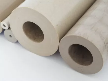
Compression molding, FDM 3D printing, and CNC machining are also widely used for producing PEEK components with different geometries, performance requirements, and production volumes.
Based on ARKPEEK's experience in PEEK materials and feedback from real-world production and technical services, this guide focuses on common processing problems, their typical symptoms, and practical recommendations for improving PEEK processing results.
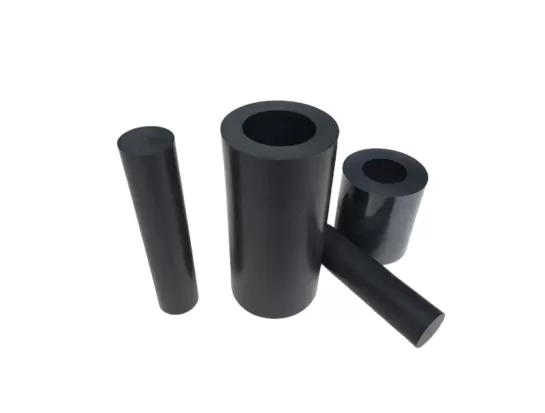
Compression molding can be used to manufacture PEEK plates, rods, and other semi-finished products. However, improper control of drying, pressure, temperature, mold conditions, or cooling can result in internal defects and dimensional problems.
The main challenges include:
Internal voids or vacuum pores
Uneven density
Flash and insufficient filling
Cracking after demolding
Surface carbonization and contamination
Typical symptom:
Voids or cavities appear inside molded PEEK plates or rods.
Recommended solution:
PEEK material should be thoroughly dried before processing. According to the supplied processing guidance, the moisture content should be controlled to approximately 0.2% before molding.
Proper material drying is an important first step for reducing internal defects during PEEK compression molding.
Typical symptom:
The edge of the molded product may not be completely filled, while excessive flash causes material to escape from the mold and can result in insufficient filling in the center.
Recommended solutions:
Properly control the mold fitting clearance, with the source guidance recommending approximately 0.05–0.1 mm.
Use a controlled or limited compression molding design and spacers to control product thickness.
Increase mold closing speed so that filling is completed before the melt begins to solidify.
Properly control molding pressure and maintain a suitable compression speed.
These measures help improve material filling and reduce pressure loss caused by excessive flash.
Typical symptom:
The molded PEEK product cracks during demolding or shortly afterward.
Recommended solutions:
PEEK compression-molded products can have high crystallinity and significant internal stress. Therefore:
Perform slow annealing, gradually cooling the material from approximately 200°C to room temperature at 10–20°C/h.
Do not forcibly demold the product while it is at a high temperature, particularly above 150°C.
Keep the mold contact surfaces as smooth as possible to allow demolding at lower pressure.
Proper thermal treatment and gentle demolding are essential for reducing cracking caused by internal stress.
Typical symptom:
The material in contact with the mold surface becomes dark, develops bubbles, or shows signs of contamination.
Recommended solutions:
Carefully control heating time and avoid prolonged heating that can cause carbonization.
Clean the mold regularly.
Control powder contamination and maintain cleanliness in the drying and processing equipment.
Store PEEK materials properly and prevent contamination during loading and handling.
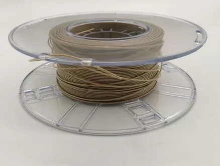
FDM (Fused Deposition Modeling) 3D printing provides a flexible method for manufacturing complex PEEK components and prototypes. However, PEEK has demanding thermal requirements, making temperature control and printing conditions particularly important.
The major challenges include:
Weak interlayer bonding
Warping and build-plate detachment
Difficult support removal
Nozzle clogging
Typical symptom:
The printed component cracks or separates between layers when subjected to mechanical stress.
Recommended solutions:
Use a heated chamber. The source guidance recommends a chamber temperature of at least 90°C, preferably 120°C or higher, to reduce temperature differences between printed layers.
Reduce printing speed when necessary and increase nozzle temperature according to the recommended filament processing parameters.
Perform post-print annealing to improve interlayer fusion and bonding.
Maintaining a stable thermal environment is particularly important for reducing interlayer separation in PEEK 3D printing.
Typical symptom:
The corners of the printed model lift during printing, or the model becomes detached from the build platform.
Recommended solutions:
Use a PEI build plate or a high-temperature adhesive coating.
Set the build-plate temperature to approximately 140–160°C according to the supplied guidance.
Add a brim to increase the contact area between the model and the build plate.
Avoid placing sharp corners directly against the build plate whenever possible.
These measures can improve adhesion and reduce thermal deformation during PEEK printing.
Typical symptom:
Support structures adhere too strongly to the printed model and damage the component during removal.
Recommended solutions:
If the printer supports it, use water-soluble support materials.
Adjust the support Z-axis/interface gap to approximately 0.2–0.3 mm.
Optimize the model design to reduce unnecessary overhangs.
Take advantage of PEEK's high rigidity by designing suitable self-supporting angles, with the source recommending angles below 45°.
Typical symptom:
The printer stops extruding material during printing or extrusion becomes inconsistent.
Recommended solutions:
Keep PEEK filament dry. The supplied guidance recommends drying at 120–150°C for approximately 4 hours.
Use a hardened steel nozzle, especially when processing carbon-fiber-reinforced PEEK, because the abrasive fibers can cause nozzle wear.
Check the heat-break cooling fan to prevent excessive heat from traveling upward and causing premature filament softening and expansion.
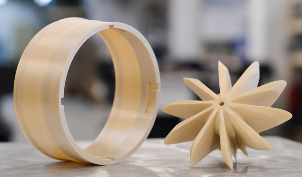
CNC machining is widely used for manufacturing precision PEEK components with complex geometries and tight dimensional requirements.
However, compared with conventional engineering plastics and metals, PEEK requires careful control of tool selection, cutting parameters, cooling, clamping, and thermal deformation.
The main challenges include:
Rapid tool wear
Burrs and edge deformation
Dimensional deviation
Poor surface finish
Typical symptom:
Conventional cutting tools become severely worn after machining only a few components, resulting in dimensional deviations.
Recommended solutions:
Use diamond-coated or CVD diamond cutting tools where appropriate.
Carbon-fiber- and glass-fiber-reinforced PEEK can cause significant tool wear. The supplied guidance recommends reducing cutting speed to approximately 100–200 m/min.
Use climb milling to reduce friction between the cutting tool and workpiece.
Tool selection becomes even more important when machining reinforced PEEK grades because the reinforcing fibers can significantly increase tool wear.
Typical symptom:
Burrs appear around drilled holes or machined edges, affecting assembly and dimensional quality.
Recommended solutions:
Keep cutting tools sharp, since dull tools are a major cause of burr formation.
When drilling through-holes, reduce feed rate before the drill breaks through the material or use a step drill.
When machining edges, use appropriate milling strategies such as trochoidal milling, or leave approximately 0.1 mm for a final finishing pass.
Typical symptom:
The component meets dimensional requirements during machining but changes size after removal from the machine or during storage.
One important factor is PEEK's thermal expansion behavior. The supplied technical guidance notes that the thermal expansion coefficient of PEEK, particularly unfilled grades, can be approximately 10 times that of metals.
Recommended solutions:
Provide sufficient cooling during machining and maintain a controlled room temperature.
For critical dimensions, perform stress-relief annealing after rough machining before final finishing.
Avoid excessive clamping force. Because PEEK has a lower elastic modulus than metals, excessive clamping can cause elastic deformation and dimensional rebound after the workpiece is released.
Typical symptom:
The machined surface appears rough, with a scale-like texture or whitening.
Recommended solutions:
Use high-pressure coolant or air cooling to remove machining heat promptly.
For unfilled PEEK where transparency or a high-quality optical appearance is required, the supplied guidance recommends diamond tooling combined with single-point cutting.
Increase spindle speed while reducing feed per revolution.
Remove chips promptly to prevent chip entanglement around the workpiece or cutting tool.
Copyright © PEEKCHINA | Taizhou Ark International Trade Co.,Ltd. All Rights Reserved |
Sitemap
| Powered by



 EN
EN